 |
By Chander Kant
The network fabric connecting the compute nodes in a cluster to carry inter-node message traffic is referred to as cluster interconnect or simply interconnect. The term System Area Network(SAN) is also sometimes used to denote a cluster interconnect. Although the scope of SANs is somewhat broader than cluster interconnects. Note that an interconnect does not hook up to the user LAN. It is completely under the administrative domain of the cluster administrator. The LAN administrator need not be even aware of the type of interconnect being used in a cluster, unless of course the same person is playing both roles. The user connectivity of the cluster is simply through a LAN connection on the head node of the cluster and does not require much design consideration.
The choice of optimal interconnect for a cluster is very important and can be very difficult to make. If the right balance is not struck between the processing power of the nodes in a cluster and the communication ability of its interconnect, the nodes will potentially waste their computing resources while waiting for data. On the other hand depending on the interconnect that you choose, it may turn out to be a significant percentage of the cost of the cluster. The research and practice in the area of high performance cluster interconnect techonology lies interestingly between MPP interconnect technologies and generic LAN technologies. A cluster interconnect is much more specialized than a generic LAN, hence providing many opportunities for performance optimization as well as ability to use network equipment without the bells and whistles needed to support a general purpose network. On the other hand a cluster interconnect, by its very nature, is more flexible than an MPP interconnect and thus e.g. cannot use highly optimized routing algorithms which assume fixed topology.
In this chapter we will present an overview of the most popular networking hardware and software packages that are being used as cluster interconnects. We will also share practical experiences with many of these technologies. Before we start talking about the particular technologies in detail, let us first go over an abstract introduction which is needed to compare and contrast various technologies. Following is not offered as Networking 101, indeed we assume basic networking knowledge, but we go over the aspects of networking most relevant to cluster interconnects.
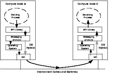
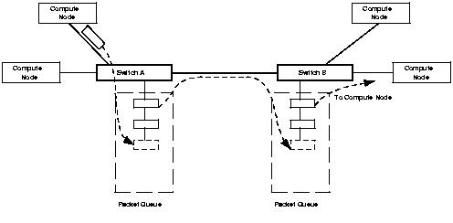
Fig 3.1 shows the path of a packet in a cluster from one compute node to another. We have simplified this model in order to explain the relevant concepts in this section, e.g. we have not shown all the various layers within the interconnect fabric itself. A process, which is part of a parallel application is running on node A and is attempting to send a message to another process running on node B. The sending process initiates the message by making a call to a parallel programming library, e.g. an MPI library. The MPI library transfers the message down to the particular protocol layer being used to implement the MPI library. This protocol layer then either passes the message directly or through the operating system on to the physical network. On the receiving side events happen in the reverse chronological order as on the sending host, ultimately providing the packet to the application process. At a physical level the packet passes from sending host's memory onto the NIC, then to the network cable, going through any switches, reaching the NIC of the receiving host, finally into the memory of the receiving host.
When designing the interconnect fabric for a Linux compute cluster the choice of Network Interface Cards (NICs) and their corresponding switches, if necessary, depends highly on the application(s) for which the cluster is being built. The key parameters of the network type that affect this choice are: Latency, Bandwidth, CPU overhead, Multithreading and, of course, cost of the network devices and required software packages. In the following sections we define each of these parameters and describe ways of comparing various choices along these parameters.
Latency refers to the time it takes for a single packet to leave the source and reach the destination. It is measured from the time the sending process sends the packet to the time the destination process starts receiving the packet. A popular way of measuring the latency of an interconnect is to have a pair of machines repeatedly send a small message back and forth. If the packet was able to make N round-trips in time T, the one-way latency of the network will be T/2N. If MPI is the programming API being used, this measured time is referred to as half-round-trip MPI latency. Program 3.1 shows an MPI program which when run on two machines provides a measure of the latency of the fabric used.
double half_round_trip_latency(int N)

{


  char packet[SMALL_PACKET_SIZE];

  double startTime, endTime;

  int i, rank;

  MPI_Status status;


  MPI_Comm_rank(MPI_COMM_WORLD, \&rank)

  MPI_Barrier(MPI_COMM_WORLD);

  startTime = get_time();

  for (i=0; i<N; i++) {


  if (rank == SENDING_PROCESS)

     MPI_Send(packet, SMALL_PACKET_SIZE, MPI_CHAR, RECEIVING_PROCESS, i,

	MPI_COMM_WORLD);


  if (rank == RECEIVING_PROCESS)

     MPI_Recv(packet, SMALL_PACKET_SIZE, MPI_CHAR, SENDING_PROCESS, i,

	MPI_COMM_WORLD, &status);


  }

  endTime = get_time();


  if (rank == SENDING_PROCESS)

     return((endTime-startTime)/(2*N));

  else

     return(0);

}
It is important to measure the latency of a fabric at an API level. Even if the underlying physical media can support very fast exchange of messages, the protocol implementation on top of the physical media can make a significant difference in the effective latency for the application. For example if the parallel programming library is implemented on top of a general-purpose protocol like TCP/IP, the packet will take a significant time to go through the various layers of the protocol to reach the physical media itself. E.g. in MPI implementations over TCP/IP data is first copied from NIC to kernel space and then from kernel space to user space. Although Linux has an excellent TCP/IP implementation, for many MPI application environments use of a light-weight protocol is desired. In sections ? and ? we go in detail of some of these light-weight protocols and their implementations.
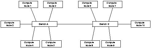
It is also important to account the affect of switches on the latency between two machines in the cluster. If messages have to go through multiple switches before reaching their destination node (fig 3.2), the latency for these messages could be significantly higher compared to point-to-point connected nodes. Such configurations also introduce different latency numbers between different pairs of nodes. For example, in fig 3.1 nodes 1 and 2 would likely have better latency between them, as compared to nodes 1 and 6, especially if the intermediate switches introduce significant latency. Implementation and scheduling of many parallel programs can benefit from knowledge of such non-uniformities, especially since many parallel algorithms have a significant amount of communication between neighbours.
How a message is viewed in the interconnect fabric and the mechanisms used to route it to its destination make a significant difference in the latency seen by the parallel applications in the cluster. In the following section we briefly summarize the routing methodologies used by various cluster interconnects.
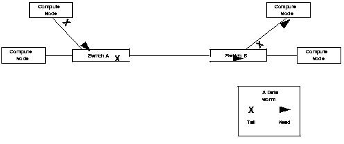
There are two distinct ways on how interconnect fabrics transmit a message. Packet switching (or store-and-forward switching) transmits a message as a packet (or a sequence of packets), with each packet being solely present at either a cluster node or an intermediate switch. In describing network topologies, the switches and hubs in the network are sometimes referred to as nodes. We would avoid such usage to avoid confusion with cluster nodes. On the other hand wormhole switching (or cut-through switching) transmits a message as a worm, i.e. a continous stream of bits which make their way through the fabric, potentially spanning multiple cluster nodes and switches concurrently.
Using wormhole based switches can significantly improve the latency characteristics of a cluster.Switches based on store-and-forward methodology wait for the whole packet to arrive before making the routing decision for next stop for the packet. There is some terminology ambiguity here as well. A technique where the routing decision of a packet is made before the whole packet arrives, but the packet is forwarded only if it is known that whole of it could be buffered at the next destination is called virtual cut-through. Wormhole switches do not have the overhead of storing whole packets before forwarding them to the next node or switch, and thus considerably decrease any latency overhead of passing through a switch.
 |
Packet switching technology (using store-and-forward mechanism) used in many LAN/WAN switches can significantly detriment latency.
Bandwidth refers to the amount of data that can flow through the interconnect fabric in a unit of time. As with latency, bandwidth should also be measured at the parallel API level, since the raw bandwidth of the physical network can be significantly higher than what the parallel application can actually realize.
There are two bandwidth numbers that need to be considered. First is the bandwidth of the network with a point-to-point link between two nodes in a cluster. Although in practice a cluster will rarely run in this configuration, this bandwidth number gives the best case scenario that a single port will support.Point-to-point bandwidth can be measured by a variant of the program 3.1, by sending large messages instead of small messages. Second number is the bisectional bandwidth of the interconnect fabric. Conceptually bisectional bandwidth is the rate of data that can be sent across an imaginary line dividing the cluster into two halves each with equal number of CPUs. Depending on how this imaginary line is drawn different bandwidth numbers can be obtained. The bisection bandwidth of the cluster is defined to be that offered by the worst case scenario. Bisectional bandwidth can get tricky to measure, in fact even difficult to define for complex network topologies.
If all the cluster compute nodes hook up to a single interconnect switch, then the cluster bisectional bandwidth is same as that of the switch. Say a switch has N ports (assuming N to be even). Now assume N/2 nodes in the cluster are sending a continuous stream of data, i.e. a very large packet, to the other N/2 nodes in the cluster. These second set of N/2 nodes are also sending a continuos stream back to the first set (this assumes network to be full duplex). The amount of data that flows through the switch per unit time defines the bisectional bandwidth of the switch. This is the maximum network bandwidth a cluster can expect if the switch in above scenario is at the center of its fabric. A non-blocking switch has the bisectional bandwidth equal to N times the point-to-point bandwidth. Bisectional bandwidth of an oversubscribed switch is less than the corresponding non-blocking switch with same number of ports. So, an oversubscribed switch may slow down a node from sending a message even if the link would allow higher bandwidth. In a cluster with very busy interconnect, with nodes having to send data out simultaneously at various times, use of a non-blocking switch may be essential. In a cluster where it is rare for nodes to be simultaneously pushing data out on the network, an oversubscribed switch may be a cost-effective choice. A critical number to note is the bisectional bandwidth per processor in the cluster. Again assuming all the nodes are connected to a single central switch, a non-blocking switch provides a constant bandwidth per processor as the number of nodes increase in the cluster. An oversubscribed switch, on the other hand, scales the bandwidth per processor upto a point after which the increase in number of nodes decreases the available bandwidth per processor.
Maintaining constant bandwidth per processor gets harder once the number of nodes in a cluster exceed the ports available in a single switch. For example, in fig 3.1 if there are no other connections between the nodes that connect to switch A and those connected to switch B, the wire connecting the two switches may become the bottleneck, limiting the total bisectional bandwidth of the cluster. One obvious way to avoid this is to use switches with higher count of ports. This is sometimes impractical because it requires investing upfront in the capacity which may get used in the future. Furthermore for bigger clusters, switches may not exist to satisfy the port requirements for all the nodes. Another way to offset at least some of this bottleneck is to use switches with faster uplinks. For example if the two switches in fig 3.2 are both 8 port Fast Ethernet switches, and the link between the two is a Gigabit Ethernet connection (see section on Ethernet), this link will likely not be a choke point anymore.
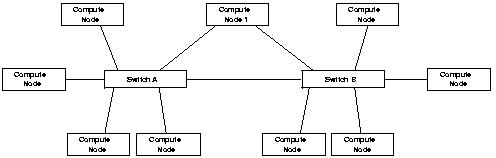
If more than two switches are needed in the interconnect fabric, or if faster uplink is not an option, more complex topologies of inter-switch connections need to be used to reduce the worst case scenarios of multiple hops. The subject of optimal network topology under different conditions has been studied fairly extensively, especially in the MPP domain. A detailed exposition of this material is out of scope of this book. Nevertheless we provide some examples of key topologies used in the technology overview below and in the last part of this book. There are many parallel applications which put higher communication load on a few selected nodes, i.e. their communication load is not evenly balanced across the cluster. If a cluster is to be tuned for such applications, an irregular topology of network links could be use e.g. multiple links can be added to a single node. E.g. in fig 3.3 all nodes are one hop away from Node 1. In this case the job scheduler will need to ensure that processes of applications are appropriately spawned to make use of such optimizations. In general we recommend using such irregular network topologies only in special cases where the cluster being deployed is going to run applications with communication skew for most of its deployment. Regular topologies result in ease of management, the allow use of well understood routing & job scheduling algorithms as well as are easy to administer.
While analyzing how the application is going to perform on a cluster it is important to consider the affect of network activity on CPU performance. If bulk of the network processing is taking place in the host CPU, then this load will compete with the load of instructions within the application itself. Many intelligent NICs try to handle various pieces of network processing within themselves, thus freeing the CPU to do application work. For a very busy interconnect this could be a critical criteria, either the NICs would need to be intelligent, or the CPU power would be required to be higher to accommodate the network load. A low CPU overhead and careful overlaping of computation with communication, allows the application to do useful work in the CPU while processing is being done on the processor embedded in the NIC. Myrinet NIC is an example of such intelligent NICs. Myrinet NIC has a processor embedded on the card, called the Lanai processor. The Lanai processor reduces the burden of the host CPU by taking over many of the network flow activities.
Another significant optimization to reduce the CPU overhead is the use of light-weight protocols. These protocols are designed to specifically ship relatively small messages across a controlled network topology like that of a cluster. Traditional protocols such as TCP/IP are designed to run on very general purpose networks and hence must take care of many exceptions and errors which are not relevant to compute clusters. The protocols used in cluster interconnects can be much more optimistic and can make various assumptions as compared to general purpose protocols. Implementation of such protocols generally requires some level of intelligence from the underlying NIC. This could be either in the form of an embedded processor, like the Lanai processor in a Myrinet NIC, or it could be in form of special firmware in the NIC. In another chapter we go into details of some popular light-weight protocols.
Multithreading refers to the ability of the network to transfer multiple messages concurrently as well as the ability of a node to use the fabric from different contexts. In a compute cluster using SMP nodes, i.e. nodes containing more than one processor, jobs may get scheduled in a way that independent applications on the same node want to use the interconnect for their message exchange. Certain NICs (and their corresponding drivers) are able to talk to multiple high level processes for message exchange, whereas some NICs are tied to a process until that process has completed its communication and relinquished the NIC.
Various factors should be considered while calculating the cost of an interconnect. The base cost of the interconnect includes the cost of NICs, switches, cables and required software libraries. There are secondary cost considerations as well. Particular choice of NIC may require higher speed host processors thus adding to the cost. A non-standard network also requires training cost, which may not required if a more commonly used network such as Ethernet is used. Availability of good driver and API implementations on a specific vendor's network options may reduce the in-house development and tuning costs.
Various flavors of Ethernet running TCP/IP protocols form the core engine of Intranets and the Internet. Currently (Mid 2000) there are three popular flavors of Ethernet differing in their peak bandwidth: standard Ethernet (commanly referred to as just Ethernet), Fast Ethernet, and Gigabit Ethernet providing 10 Mbps, 100Mbps, and 1000Mbps of peak theoretical bandwidth respectively. Most desktops today (Mid 2000) connect to their local area networks using Ethernet. Fast Ethernet is catching up very fast, and is the dominant connectivity mechanism for the new backend servers. web servers, fileservers etc. Gigabit Ethernet is gaining rapid acceptance as the backbone network connecting switches together, as well as a connection into heavily accessed back end servers. The successive members of the Ethernet family benefit tremendously from the install base of previous generation. E.g. the Gigabit Ethernet over copper can use the same cable (CAT-5, using 1000Base-T) as being used for Fast Ethernet based networks. Upgrading a server from Fast Ethernet to Gigabit Ethernet does not require a change in network topology. Organizations can leverage on their current infrastructure, network management tools, and personnel to add needed bandwidth at moderate upgrade costs. These factors have made Ethernet and Fast Ethernet very much commodity components, with Gigabit Ethernet heading that way as well. By one estimate more than 1.4 million Gigabet Ethernet switch ports were expected to ship in first half of year 2000 alone[3].
Omnipresence of various flavors of Ethernet and their relatively low cost makes Fast Ethernet and Gigabit Ethernet key contenders to be used as cluster interconnect fabric. Although Standard Ethernet is still a very popular port on desktops, it is fading away as a server networking option. Even most of the low end servers ship with a standard Fast Ethernet port. So, unless you are redeploying old PCs as cluster nodes, standard Ethernet need not be considered as an option. From this point on we will use the term Ethernet to describe Fast Ethernet and Gigabit Ethernet networks. Among all the various interconnect options being discussed here, only Ethernet truly meets the Beowulf philosophy, in that it is a commodity hardware using standard protocols and is manufactured by multiple vendors. On the other hand the very omnipresence of Ethernet prevents it from being the most optimized interconnect fabric for a high performance compute cluster. In next few sections we go over some of these trade-offs.
Although Fast ethernet switches are coming down in price very aggressively, a repeater hub is still much cheaper than a switch. For clusters where bisectional bandwidth and scalability of the cluster are not of much concern, use of a hub can be considered. This is true for cases where the parallel application(s) running on the cluster make very infreqent and small exchanges of information, or if the cluster is being primarily run as a throughput cluster.
Others: SCI, Giganet, GSN, ATM as interconnect between clusters, e.g. in grid environment.
Latency is particularly important for a capability cluster, which is built for an application highly sensitive to speed of exchange of messages across cluster nodes. E.g FIND Example. Applications containing a lot of remote-reads or blocking remote-writes are usually latency sensitive. There are various programming techniques to hide the effect of latency on the application. For a discussion of such techniques used in MPI based programs see section . Also note that bandwidth, at least to a limited extent, could be added to an interconnect by adding multiple paths, but reducing latency requires a change in techonology, either in the type of network hardware or in the software protocols being used.
For some clusters the application requirements may not dictate the highest bisectional bandwidth for the interconnect. In many cases most of the applications running on the cluster do not span all of the compute nodes present in the cluster. If a particular cluster installation has majority of its applications confined to a few compute nodes, and only very few non-critical applications requiring a vast span, the bandwidth of such a cluster need not be optimized for the weakest link in its interconnect. As long as the job scheduler is intelligent enough to deploy the parallel applications such that all their processes run on nodes with close proximity (e.g. connected to the same switch), the cluster usage may prove to be optimal.
[3] InternetWeek Feb 28, 2000